Monday, May 28, 2012

Memorial Day update ...

Time for another update ...

Tires:
Big news is that we've got tires ... and it's starting to look more like a real car.  Jared's friend Brad Tucker ( of Tucker Tire in Laguna Hills) hooked me up with a great deal on some Nitto NT 555's (315/35/17 on the rear and 255/40/17 on the front.  Big, wide and sticky tires on my Hallibrand replica wheels.  Ought to be perfect!  Many thanks Brad for helping make them available - and thanks to Jared and Jen (and Jen's sister Kim) for bringing them up to St George when I couldn't get down there to pick them up.
Nitto tires .... with a bonus can of Diet Coke
("I'm not addicted to Diet Coke.  I can quit drinking it anytime, I just don't want to!")
Almost lost my tires when they became "cars" for the little girls (Laney and Megan)

Nitto tires mounted on the Hallibrand wheels (minus spinners) and on the car.
Starting to look like a real car!
Jared with Jen's sister Kim in the shop

Aluminum Panels - cockpit area:

Before the tires arrived, with the fuel and brake lines done, I was working on the cockpit aluminum panels when I realized I'd need to get "under/behind" the cockpit panels to install the wiring harness - so I stopped installing panels ... at least till the wiring is closer to being done.
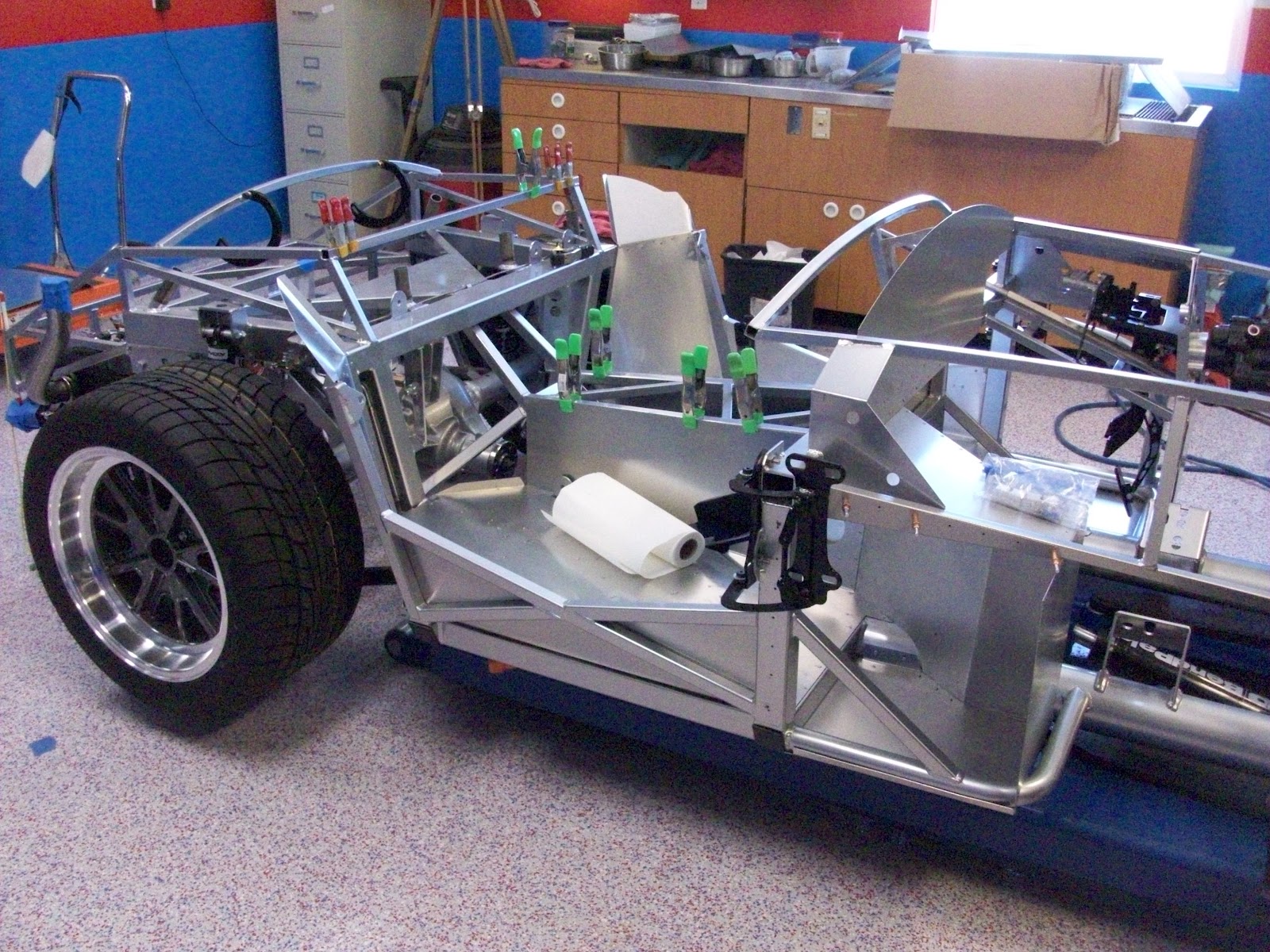
Progress on the cockpit aluminum panels - floors and rear corners done
Cleco's (temporary fasteners) are cool!
Rear bulkhead of cockpit just sitting in place (not installed).

Starting Electrical/Wiring:
The supplied wiring harness is custom made for the car - but is still gonna be a challenge to get installed.  Some of the harness elements (ends/connectors) don't seem to end up in the right places on the car, and will need to be modified a bit ....

The black "snake" is the wiring harness (part of it!) sorta draped onto the chassis to check for placement.
It needs to be modified for better fit ....

Part of the harness laid out on the bench for dis-assembly and modification (!)

So I'm busy gathering/ordering parts needed to modify the harness - terminal strips, crimp connectors w/heat shrink, crimping tool, under dash courtesy lights and so on.  Not to mention an after-market self-cancelling turn signal module (from Russ Thompson), and a push button start-stop system (Watson StreetWorks).  Additionally, the glove box "kit" is on it's way here from Oregon

As a side note - while I love living in St George, some (most!) of the stuff electrical stuff I need is just not available locally.  Not to mention the proper type (thickness and temper) aluminum sheet for some modifications which is simply not available except as a full 4 x 8 sheet - which I can't handle and which "they" can't cut into smaller sheets.

So the "Google is my friend" for locating & ordering stuff .... and the UPS guy is my friend getting stuff to me.

Part of the electrical install is finalizing the dash elements and their layout.  Rather than using the FFR supplied "street dash", I'm using a "Competition dash" that I got from my friend Luis in Santa Clarita (who's also building a Mk 4 "Anniversary" Roadster.

The "street dash has the tach and speedo in front of the driver, but the Competition dash has the tach in sorta in front of the driver and the speedo toward the middle of the dash (so the passenger can see it! -- LOL)

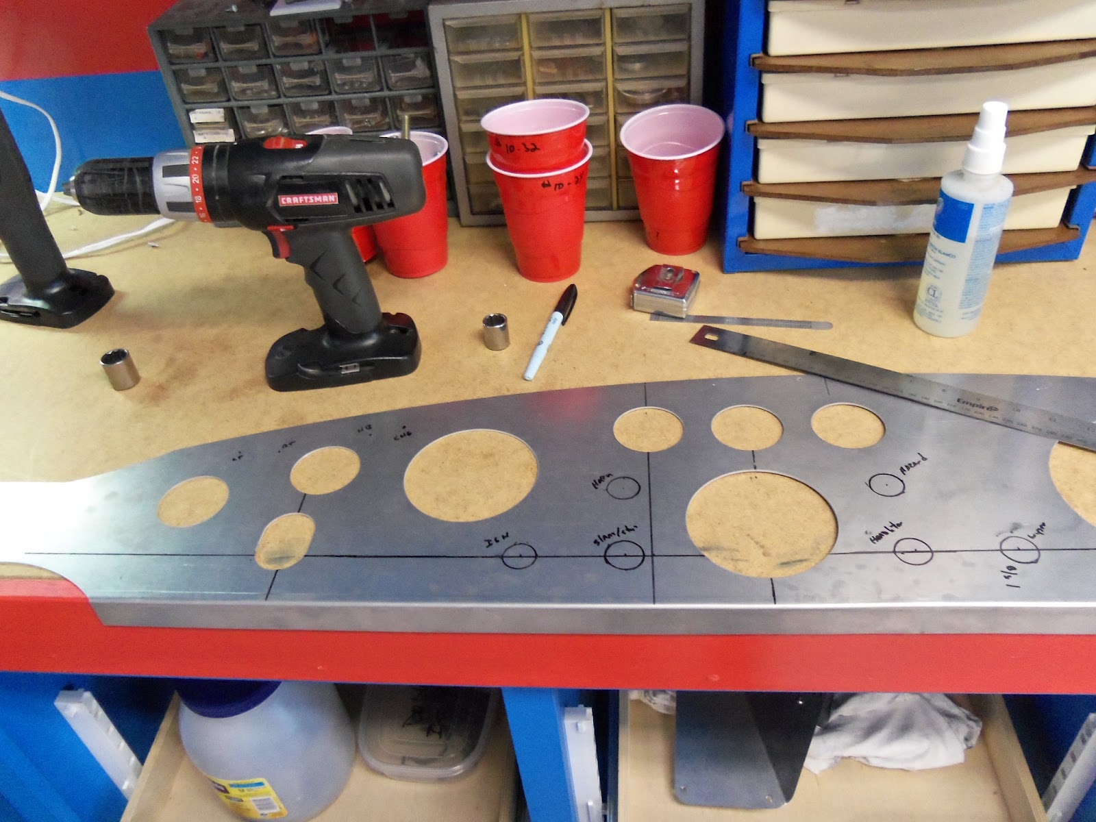
So using the white board, I'm laying out location for switches .... ignition, start-stop, headlights, wipers, horn and hazard lights (4-way flashers). Plus left-right turn signal and high beam indicators.

Comp dash temporarily clamped in place on the chassis

Laying out switch locations on the white board ....

And transferring locations to the dash.  I have to start drilling holes pretty soon --- and it's gotta be right!

Switches for seat heaters, fan over-ride, master disconnect, a clock, 12 volt "power ports" and iPod controls will be on a small console panel just below the center of the dash.

This is kinda the "model" for my dash  .... at least for the under dash "console" (this Cobra has the "street dash").
I'm planning cup-holders and a transmission "mid-shift" as is also shown.

Lessons:
Lots of lessons are being learned while building my car.  Among them are "patience", "walking away" once in a while, the value of research .... there are hugely valuable Forums on the web, like "FFcars.com" ... and that everything does not go as planned.

Lessons "learned" and to be remembered!
More later when there's progress on the electrical ....  soon I hope!!

Thursday, April 5, 2012

Early April update - WHERE HAS THE TIME GONE????

Realized it's been ages since I updated the blog,and while it may not seem like much has happened, it's been pretty busy behind the scenes!  So let's get caught up ....

Power brakes:
We decided to go with hydroboosted PB's - which uses power steering fluid pressure rather than a vacuum booster as is used in most cars - so no cutting/patching of the frame was needed.  The hydroboost brake conversion pieces arrived in mid-January and the master cylinder (MC) "fitment" saga began! 
First MC to arrive was much too long and would have significantly interfered with aluminum panels to be installed later, and the brake line attachment "ports" were on the wrong side  ... toward the fender rather than toward the engine, making it difficult to attach brake lines.  Would have made it necessary to "just cut a hole in the <future> panel and make a patch".  Unacceptable.
1st hydroboost master cylinder was too long and the outlets were on the wrong side

So we worked with the supplier and got a somewhat shorter MC but which had the brake line "ports" on the engine side.  All of which meant easier installation of brake lines - but a hole/bump-out in future aluminum panels would still be needed. 
2nd master cylinder was just a bit shorter, but had the outlets in the right place (on the side you can't see)

More investigation and talking to people resulted in finding a much shorter MC with holes in the right places  - so it looks like no hole in the front panel will be needed. I shared this latest MC "find" with local friends who retro-fitted the shorter MC into a finished car, and it fit great, no hole was needed .... so we're moving on!
3rd (and final!) master is shorter so it fits much better and is already set up for remote fluid reservoirs

 Aluminum panels:
With the brake thing sorted out and finalized, we were able to complete test fitting of the engine bay aluminum panels - esp. the one in front of the driver side foot box, and send them out for powder coating.  After a lot of discussion, we decided to go with a 'sparkle silver' powder coat to match the powder coated chassis.  Much prettier than 'bare' aluminum or clear coated aluminum.  Other panels - in the cockpit and trunk - will be not be seen (but will be covered with carpet and etc) so they'll just get a coat of an aluminum preservative/exterior treatment called "Sharkhide".

Powder coated firewall riveted and installed!

Passenger side foot box - powder coated and installed
Passenger side foot box and the firewall are installed and permanently riveted, along with some of the drive side foot box. 

The outer wall of both foot boxes will be installed just before installing the body - which will make it much easier to install the insulation and carpet into the foot boxes.  (Thanks Jared for suggesting this.  It's a great idea!)

We also got the battery box moved from the trunk to the front of the engine bay.  It'll make for much short battery cables, and a bit more room in the trunk.
Front battery box - installed

Brake and fuel lines:
Talk about frustrating!  I've no prior experience in bending brake or fuel lines, never needed to do it before .... and trying to do it on the Cobra .... even with the right tools ... really kicked my butt!

But they had to be done before I could move on to more aluminum panel installation and the wiring and engine/transmission installation and so on.

So I finally bit the bullet and called in a friend from a local custom shop to give me a hand.  Wayne Glasgow spent about 6 hours and did a GREAT job bending and installing the lines.  I wish I had his skills and expertise!

Wayne Glasgow - the fuel and brake line master - at work!
Fuel supply and return lines at the rear fuel filter

Fuel lines (not yet painted) coming down the rear chassis member to the 4 inch tubes and then forward
Fuel lines in the engine bay
 The fuel lines will be removed for painting (the black lines don't look good against the silver chassis) and I'm missing a few more clamps which are on order.

For the brake lines, we used a relatively new product called "cunifer" - which is a DOT approved alloy of copper/nickel/steel - and which is used in Europe on high end cars like Mercedes, Porsche, Volvo and etc.  It is  much easier to bend by hand and can be polished to a soft, golden color - which will look good against the silver chassis.
Cunifer brake lines at the master cylinder
Brake lines going up the driver side rear chassis member to the rear brakes (blue thing is a residual valve to help balance the brakes front-to-rear)

Brake lines at the passenger side rear wheel
Brake lines at the driver side front corner
Front brake line cross over from driver side to passenger side

Engine:
While all this has been going on, I've been working on needed parts for the engine rebuild - which Wayne will also be doing for me.  Another local good friend - John Towle - has been involved with the automotive performance industry for many years, and was kind enough to help me get some great parts and great prices ...
Edelbrock aluminum cylinder heads and water pump
"Petey approved" MSD distributor and ignition
Newly introduced MSD electronic fuel injection - which will "look like a traditional carborator but give modern reliability & performance!"
COMP Cams cam and timing gear and Stage 8 exhaust fasteners
ARP bolts and COMP Cam lifters

Great aftermarket parts and a skilled engine builder should make the targeted 350-ish horsepower a piece of cake!

Other stuff ....

Decided to do a hydraulic clutch instead of the "stock" clutch operated cable.  Should make clutch operation much smoother and much more reliable - since there'll be no cable that can break!  A clutch master cylinder (originally was to be one of the "stock" non-power brake master cylinders has been install in the pedal box has been installed in the driver side foot box.
Installed pedal box and clutch master cylinder

That's it for now. 

I really ought to be able to speed up the build now that the brake and fuel lines are behind me.

The kit will be one year old on 23 September and Carol's birthday is 3 August, and she'd really like to take a ride to the local In-n-Out in the Cobra for a burger on her b-day! 

Which should be do-able is I get my act together!

Stay tuned!

Tuesday, January 3, 2012

Happy New Year's!

Where has the time gone?  It's been weeks since I updated the blog, and there has been progress on the build .... along with Thanksgiving, birthdays, Christmas and New Years.  A busy time, and a good time.

So here's what's happening on the Cobra ...

I posted pictures of the 89 Mustang "donor" car earlier.  Jared and Jen came up one weekend, and Jared helped me pull the engine and transmission so they can be gone thru and "warmed up" a bit.  Target is for 325 - 350 horsepower, which ought to be plenty for the 2,200# car ......
Freshly extracted engine and transmission from the donor car
After pulling the engine / transmission, with all the transmission oil that came out, it looked like the Exxon Valdez oil tanker had run aground near the car.
Anyone see a big oil tanker in the area .... leaking oil?
But after a bit of diatomaceous earth was used to absorb the oil, it looks good-as-new.

Concrete slab is now clean and good-as-new!
The engine and transmission have been taken to my engine builder (Wayne Glasgow at SKJ Customs here in St George) for tear down and examination prior to being rebuilt and "warmed up".  More on that later ....

Power steering
Not part of the supplied parts with the kit - but something I wanted is power steering.

Through my research, I determined that a 3 turns "lock-to-lock" PS rack would likely be best for my planned use of the completed car.  After several unsuccessful tries using a local auto parts store (they kept giving me 2.5 turns PS units that were marked as 3 turns), I finally secured an acceptable PS rack that is 3 turns LTL and got it installed.

PS rack powder coated silver to match the chassis
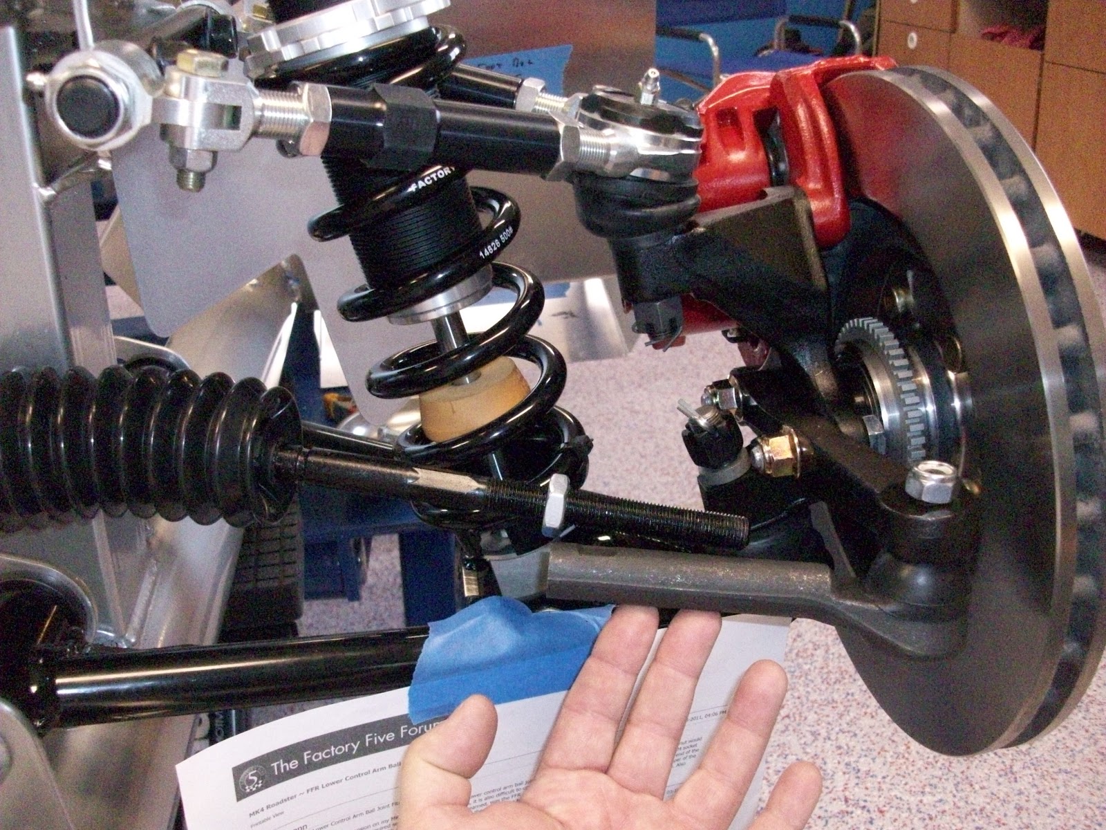
Because of the chassis geometry, the inner tie rod ends need to be shortened by approx 1 - 1 /14 inches.  I cut them by 1 inch figuring they can be shortened a bit more if needed when final alignment is done.
Before cutting the inner tie-rods .... both wheels turn out!

After cutting the tie-rods .... better, but room for some improvement when it's at the alignment shop

Heater and glove-box

Like most projects of this type, we've got a list of things we want to add to the car .... like a functional glove-box 

Dash clamped in place with a cardboard glove-box mockup
 And a heater .... but unfortunately, the glove-box and the heater want to be in the same place on and behind the dash on the passenger side.  :( 

To show the problem, here's a picture of the dash clamped in place - with cardboard mock-ups of the box holding the heater core, and a mocked-up 3 inch deep glove-box.  There are shallower glove-boxes available  .... like 1 1/2 inches deep .... but we want the glove-box to be truly functional - more than just a place to hold the registration and etc.

Not much space between the glove-box (cardboard mock-up) and the heater core box (cardboard mock-up)
Most heaters have rear facing heated air outlets - which means they'd go right through the glove-box.
typical heater with rear facing heated air outlets
typical heater with heater hoses coming out the rear
After spending lots and lots of time searching and taking to people, I couldn't find a heater that had the heated air outlets coming out of the ends of the heater core box, and was small enough to fit in the space between the glove-box and firewall.

I even considered building my own custom heater core box and using a custom made (very small and costly) heater core, or moving the firewall forward a couple of inches.

At the end of the day - after a lot of discussion with Carol - we decided to forego the heater, but to still plan for heated seats and places to plug-in electric car blankets.  We're also thinking we'll NOT plan to drive the Cobra when it's snowing or is really cold!  That should be relatively easy considering where we live!

Passenger side foot-box

When I rode in a Cobra built by a friend in Salt lake a couple of months ago, I became concerned about how big the "foot-box" area is on the passenger side (the "foot-box" is where your feet go when riding in the car).  Here's what the "stock" foot-box looks like on the passenger side .... note location of the curved chassis bar in front of the foot box ...

I applied lots of blue painter tape when the kit arrived to help identify the aluminum panels ...


So I spent a lot of time thinking about and researching how to make it larger.  And made templates for replacement panels that would push the front of the PS foot-box forward  a couple of inches ....

I looked at extensions of the existing panels panels ....
lots of blue tape is also used to protect the chassis powder coating during the build
and at a set of completely new panels ...
cardboard templates of completely new, larger panels
But I had great difficulty getting new panels to fit properly, and began to get concerned about "ripple effects".  For example, extending the foot box forward  .... forward of that curved chassis bar .... starts to get into the area where the headers will go .  And that would be a BIG problem .....

So - Carol & I talked more and agreed to go with the "stock" OEM/FFR PS foot-box size.  Many, many FFR Roadsters have been built using the panels supplied with the kits with no complaints or problems for passengers plus she's several inches shorter than I - and we decided to stick with the stock foot-box and move on with the build.


Aluminum panels

Jared and Jen were here for Christmas - and Jared and I spent a bunch of time starting installation of the aluminum panels.  Note that initially, all of the panels are located and drilled, and fastened on a temporary basis using cleco's (spring loaded clamps).

After all of the panels are fastened in this manner, they'll be removed and taken to be powder coated.  Final installation is with rivets and adhesive sealing, resulting in a solid and rattle-free final structure.

With Jared's help, we got the firewall drilled and cleco'd and most of the PS foot-box done as well.
Installing cleco's on the firewall
drilling for cleco's on PS foot-box panels
Inner PS foot-box "lid" and firewall cleco's in place

Cockpit side of PS foot-box area
Looking into the PS foot-box

Being able to elevate the chassis to a comfortable working height using the scissors lift is a huge help/luxury ....

What's next ....?

Ran out of cleco's ... so more are on order.  They're not needed in every rivet hole, but I need a few more so I can do the driver side foot-box and (finally) get the panels to the powder coater.

We've decided to add power brakes as well, which with requires modifying (cutting!) one of the chassis tubes to allow for a vacuum booster or using a newer hydroboost PB system.   I'm not fond of modifying (cutting!) the powder coated chassis, so a hydroboost system is on order and should be here shortly. 

After the PB's comes the steering column and bending installation of brake line and fuel lines ..... and more aluminum panels (drilling and cleco's on a temporary basis) in the cockpit and trunk area.

Stay tuned .....