So here's what's happening on the Cobra ...
I posted pictures of the 89 Mustang "donor" car earlier. Jared and Jen came up one weekend, and Jared helped me pull the engine and transmission so they can be gone thru and "warmed up" a bit. Target is for 325 - 350 horsepower, which ought to be plenty for the 2,200# car ......
| Freshly extracted engine and transmission from the donor car |
 |
| Anyone see a big oil tanker in the area .... leaking oil? |
 |
| Concrete slab is now clean and good-as-new! |
Power steering
Not part of the supplied parts with the kit - but something I wanted is power steering.
Through my research, I determined that a 3 turns "lock-to-lock" PS rack would likely be best for my planned use of the completed car. After several unsuccessful tries using a local auto parts store (they kept giving me 2.5 turns PS units that were marked as 3 turns), I finally secured an acceptable PS rack that is 3 turns LTL and got it installed.
 |
| PS rack powder coated silver to match the chassis |
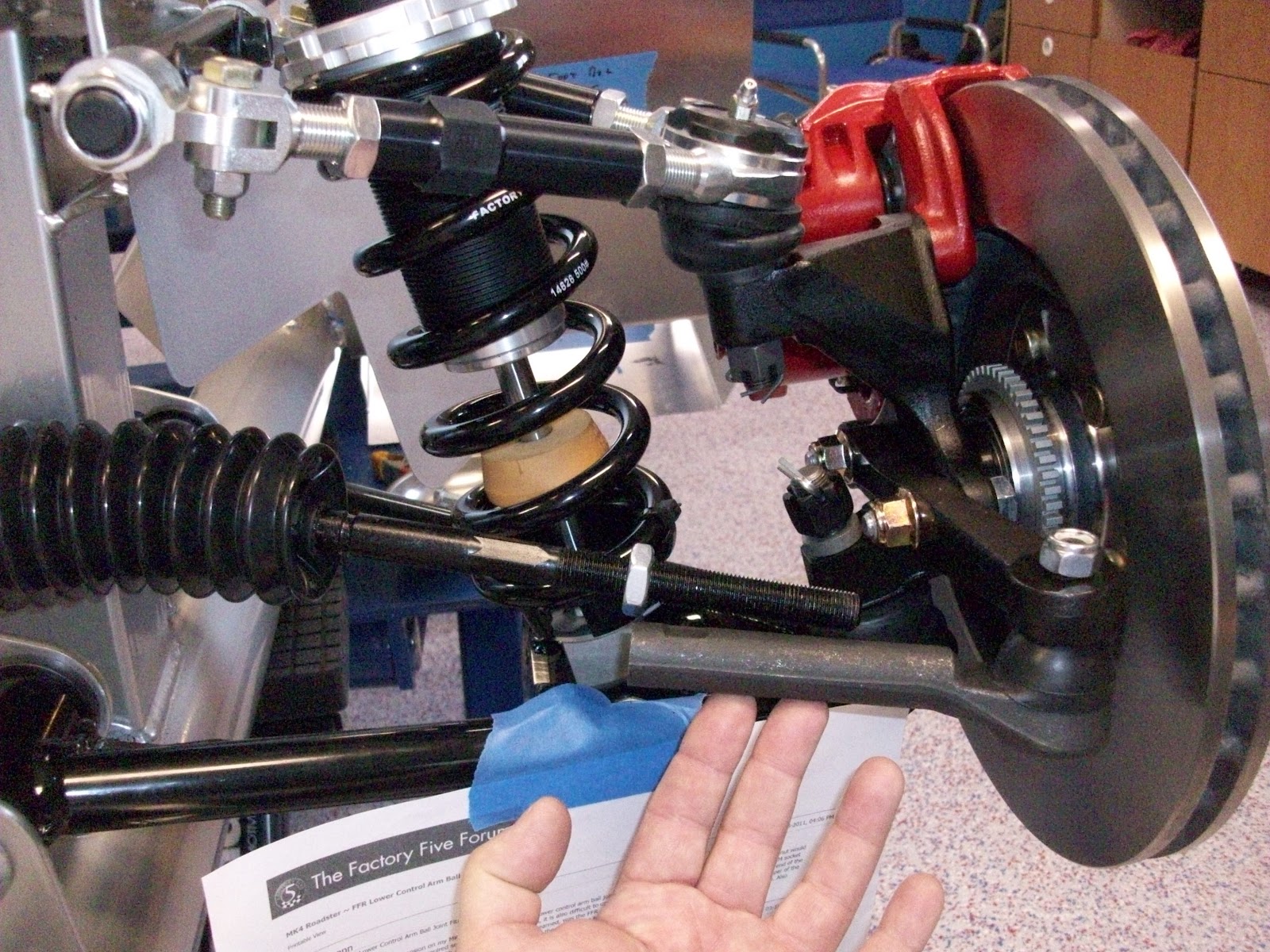 |
| Before cutting the inner tie-rods .... both wheels turn out! |
 | |
| After cutting the tie-rods .... better, but room for some improvement when it's at the alignment shop |
Heater and glove-box
Like most projects of this type, we've got a list of things we want to add to the car .... like a functional glove-box
 |
| Dash clamped in place with a cardboard glove-box mockup |
To show the problem, here's a picture of the dash clamped in place - with cardboard mock-ups of the box holding the heater core, and a mocked-up 3 inch deep glove-box. There are shallower glove-boxes available .... like 1 1/2 inches deep .... but we want the glove-box to be truly functional - more than just a place to hold the registration and etc.
 |
| Not much space between the glove-box (cardboard mock-up) and the heater core box (cardboard mock-up) |
 |
| typical heater with rear facing heated air outlets |
 |
| typical heater with heater hoses coming out the rear |
I even considered building my own custom heater core box and using a custom made (very small and costly) heater core, or moving the firewall forward a couple of inches.
At the end of the day - after a lot of discussion with Carol - we decided to forego the heater, but to still plan for heated seats and places to plug-in electric car blankets. We're also thinking we'll NOT plan to drive the Cobra when it's snowing or is really cold! That should be relatively easy considering where we live!
Passenger side foot-box
When I rode in a Cobra built by a friend in Salt lake a couple of months ago, I became concerned about how big the "foot-box" area is on the passenger side (the "foot-box" is where your feet go when riding in the car). Here's what the "stock" foot-box looks like on the passenger side .... note location of the curved chassis bar in front of the foot box ...
 |
| I applied lots of blue painter tape when the kit arrived to help identify the aluminum panels ... |

So I spent a lot of time thinking about and researching how to make it larger. And made templates for replacement panels that would push the front of the PS foot-box forward a couple of inches ....
I looked at extensions of the existing panels panels ....
 |
| lots of blue tape is also used to protect the chassis powder coating during the build |
 |
| cardboard templates of completely new, larger panels |
So - Carol & I talked more and agreed to go with the "stock" OEM/FFR PS foot-box size. Many, many FFR Roadsters have been built using the panels supplied with the kits with no complaints or problems for passengers plus she's several inches shorter than I - and we decided to stick with the stock foot-box and move on with the build.
Aluminum panels
Jared and Jen were here for Christmas - and Jared and I spent a bunch of time starting installation of the aluminum panels. Note that initially, all of the panels are located and drilled, and fastened on a temporary basis using cleco's (spring loaded clamps).
After all of the panels are fastened in this manner, they'll be removed and taken to be powder coated. Final installation is with rivets and adhesive sealing, resulting in a solid and rattle-free final structure.
With Jared's help, we got the firewall drilled and cleco'd and most of the PS foot-box done as well.
 |
| Installing cleco's on the firewall |
 |
| drilling for cleco's on PS foot-box panels |
 |
| Inner PS foot-box "lid" and firewall cleco's in place |
 |
| Cockpit side of PS foot-box area |
 |
| Looking into the PS foot-box |
Being able to elevate the chassis to a comfortable working height using the scissors lift is a huge help/luxury ....

What's next ....?
Ran out of cleco's ... so more are on order. They're not needed in every rivet hole, but I need a few more so I can do the driver side foot-box and (finally) get the panels to the powder coater.
We've decided to add power brakes as well, which with requires modifying (cutting!) one of the chassis tubes to allow for a vacuum booster or using a newer hydroboost PB system. I'm not fond of modifying (cutting!) the powder coated chassis, so a hydroboost system is on order and should be here shortly.
After the PB's comes the steering column and bending installation of brake line and fuel lines ..... and more aluminum panels (drilling and cleco's on a temporary basis) in the cockpit and trunk area.
Stay tuned .....